Free DIY guide
Build your own LaunchLab
Order the parts, then print, wire and flash it in about an evening.
LaunchLab · Top Mount v19
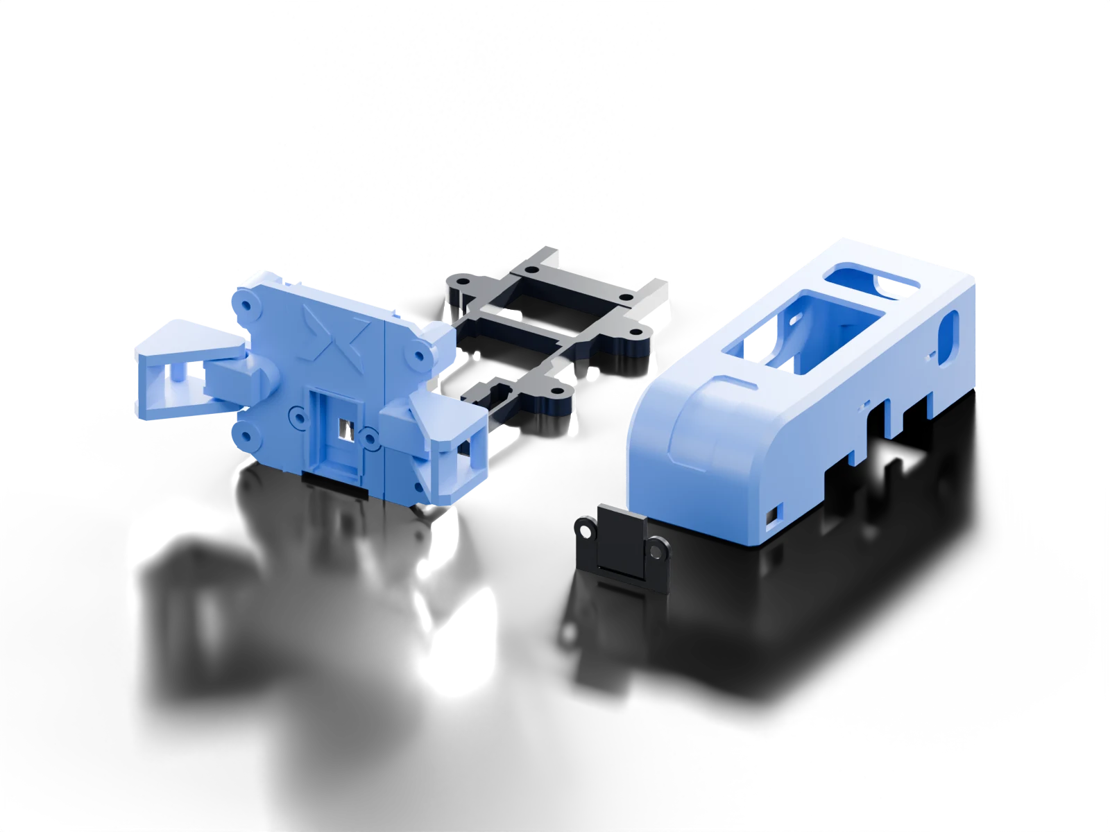
Reprint the v19 launcher clamp base with its captive clamps. Reuse the matching v18 M5 cradle, M5 snap cover and countersunk sensor retainer. The lowered middle is 18.2 mm wide with straight sides.
- 1 h 43 minprinting · 22 g PLA
- ≈$74parts to buy · details below
- 8screws · 2× M2×4, 4× M2×5, 2× M2×3
- 4printed pieces · captive clamps included
Before you start
Parts list
“Exact part” links are the parts I built and tested with.
≈$74to buy the parts for this build
Includes the analog QRE board from SparkFun ($4.08, shipping extra).
The comparison estimate includes full component packs and a 1 kg PLA spool. PETG is recommended; its purchase price may differ. Shipping, tax, solder, tools and printer access are extra. The four M2×5 M5 cradle screws and two M2×3 countersunk sensor retainer screws are also extra; their prices are not included in this estimate.
What’s in the estimate
| Item | From | Price |
|---|---|---|
| M5StickS3 K150 | Amazon | $31.90 |
| SparkFun QRE1113 analog (ROB-09453)From SparkFun; shipping is extra. | SparkFun | $4.08 |
| 8 cm male-to-female jumpers, 40-pack | Amazon | $8.99 |
| 2.54 mm right-angle headers, 10 × 40 pinsNeeds soldering to the QRE board. | Amazon | $7.59 |
| M2 pan-head screw kitFor the M2×4 screws. Buy four M2×5 bracket screws separately; their price is extra. | Amazon | $7.99 |
| PLA 1.75 mm, 1 kg spoolA build uses about 15 to 28 g of it. | Amazon | $12.99 |
| Total | $73.54 | |
One-time prices from public listings, checked October 9, 2026; they change. Assumes access to a 3D printer and basic tools, including a soldering iron for the QRE header.
Point at a part to find it in the build
Components
- 1
M5StickS3 K150
ESP32-S3 with 8 MB of flash, a display, an IMU and a battery. It stays in its case. The StickC, C Plus and C Plus2 are different boards.
- 3
8 cm jumper wires
3 male-to-female leads, about 8 cm long. Route them through the mount’s wire opening and keep slack clear of the clips.
- 1
SparkFun QRE1113 analog · ROB-09453
Use the analog ROB-09453 board so the firmware can monitor raw sensor readings and calibrate RPM measurements in software. Digital and capacitor-timing boards, including the ROB-09454, may also work, but I haven’t tested them. If you try one, please let us know how it goes!
- 3 pins
2.54 mm right-angle header
Solder it to the QRE pads so the plugs lie flat and point out past the M5’s Hat end.
- 2
M2×4 pan-head
2 screws for M5 to M5 cradle, from below.
- 4
M2×5 pan-head
4 screws for M5 cradle to four 33 × 24 mm mounting pilots.
- 2
M2×3 countersunk DIN 965 / ISO 7046
2 screws for QRE sensor retainer; 90° heads no wider than 3.8 mm.
Raw materials
PETG filament · recommended
1.75 mm. Prefer PETG for the mounts, especially captive clamps, M5 cradle snap arms and parts that receive screws. Use the matching PETG project where supplied. For a PLA-only release, open its saved 3MF as a project, select your printer and PETG profile, keep all modifier and blocker objects, and reslice. Do not print saved PLA G-code with PETG.
Solder
A little electronics solder for the three QRE header joints.
Tools & equipment
3D printer
Any good FDM 3D printer is fine. The supplied projects use a 0.4 mm nozzle and 0.2 mm layers; open the saved 3MF project, retain its modifiers and support settings, select your printer and filament profile, and reslice.
Soldering iron
We recommend the PINE64 PINECIL V2 for soldering the QRE header. It needs a compatible USB-C PD power supply and cable.
Small screwdriver
A driver that fits the screw heads used by your build.
USB-C data cable
Use a USB-C data cable you already have to flash the firmware.
As an Amazon Associate, BEYWATCH.GG earns from qualifying purchases. Amazon links use the beywatchgg-20 tag and support the project at no extra cost to you.
Print files
What you print
Printer settings
- Material
- PETG recommended; open the TCRT PLA 3MF, select PETG and reslice with its blockers retained
- Nozzle / layers
- 0.4 mm · 0.2 mm layers
- Walls / infill
- Use the supplied plate settings
- Supports
- M5 cradle: off; other parts: supplied slim tree supports
- Adhesion
- Use the supplied brim where included
- Keep
- All supplied support blockers; keep hinges and snap arms clear
The P1S projects were sliced and audited. Top Mount v19 includes 4 QRE print units; Sidecar v7 includes 6. The 3-unit Sidecar mount update excludes the sensor. Keep the M5 cradle support-free and retain every modifier and blocker object. Prefer the matching supplied PETG project. The TCRT sensor has a saved PLA 3MF only: open it as a project, select your printer and PETG profile, retain both HINGE SUPPORT BLOCKER objects and reslice. Do not print its saved PLA G-code with PETG. Prusa geometry projects need slicing. When changing printers, retain the saved project’s modifiers and support settings, then reslice.
For the three-part Sidecar mount, open the complete Sidecar PETG project, keep the Sidecar launcher adapter, M5 cradle and M5 snap cover with their attached modifiers, remove the QRE launcher clamp base, sensor retainer and Sidecar sensor cover, then reslice.
Assembly
Step by step
Part names
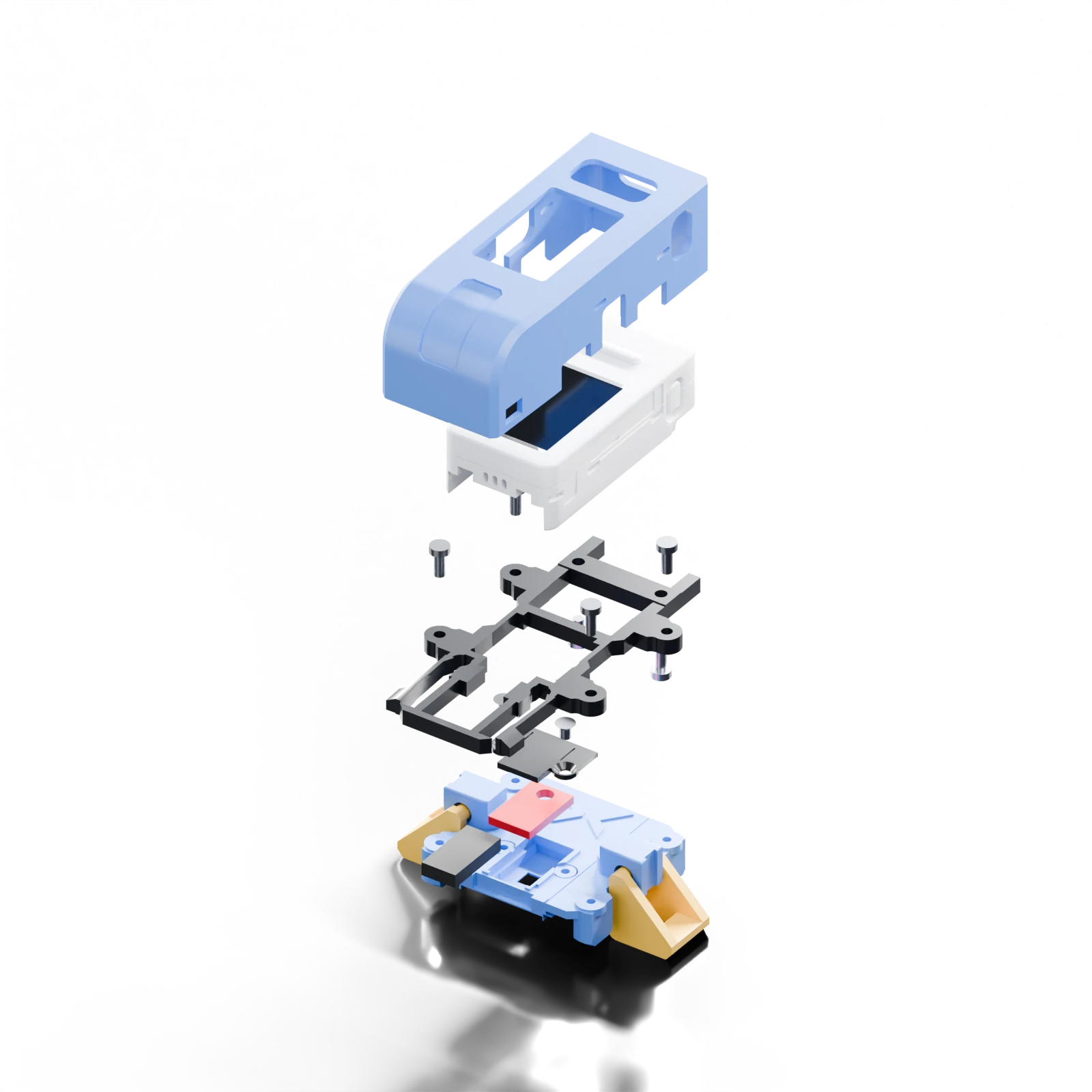
- Launcher clamp base
- Holds the QRE sensor and captive moving clamps.
- Sensor retainer
- Secures the QRE board; called keeper or pressure bar in the source files.
- M5 snap cover
- The removable outer shell.
- M5 cradle
- The M5 support, called bracket or dock in the source files. Use the cradle supplied with your selected release.
- Sidecar launcher adapter
- Attaches the separate M5 assembly to the launcher.
- Sidecar sensor cover
- Covers the separate QRE sensor and wiring.
- 01
Print the Top Mount v19 QRE kit
4-unit complete PLA plate; preserve supplied object settings.
Details
- PETG is recommended for the mounts, especially captive clamps, M5 cradle snap arms and parts that receive screws.
- Use the matching supplied PETG 3MF project for PETG. Retain all modifier and blocker objects, per-object support settings and captive-clamp positions when changing printer profiles, then reslice.
- The M5 cradle uses five walls, 35% infill and no supports. Keep the supplied settings for the M5 snap cover, launcher clamp base and Sidecar launcher adapter.
- For another printer, open the saved project in a compatible slicer, retain its modifiers and support settings, select your printer and PETG profile, and reslice. Check the preview for clear hinge gaps and snap arms.
 02
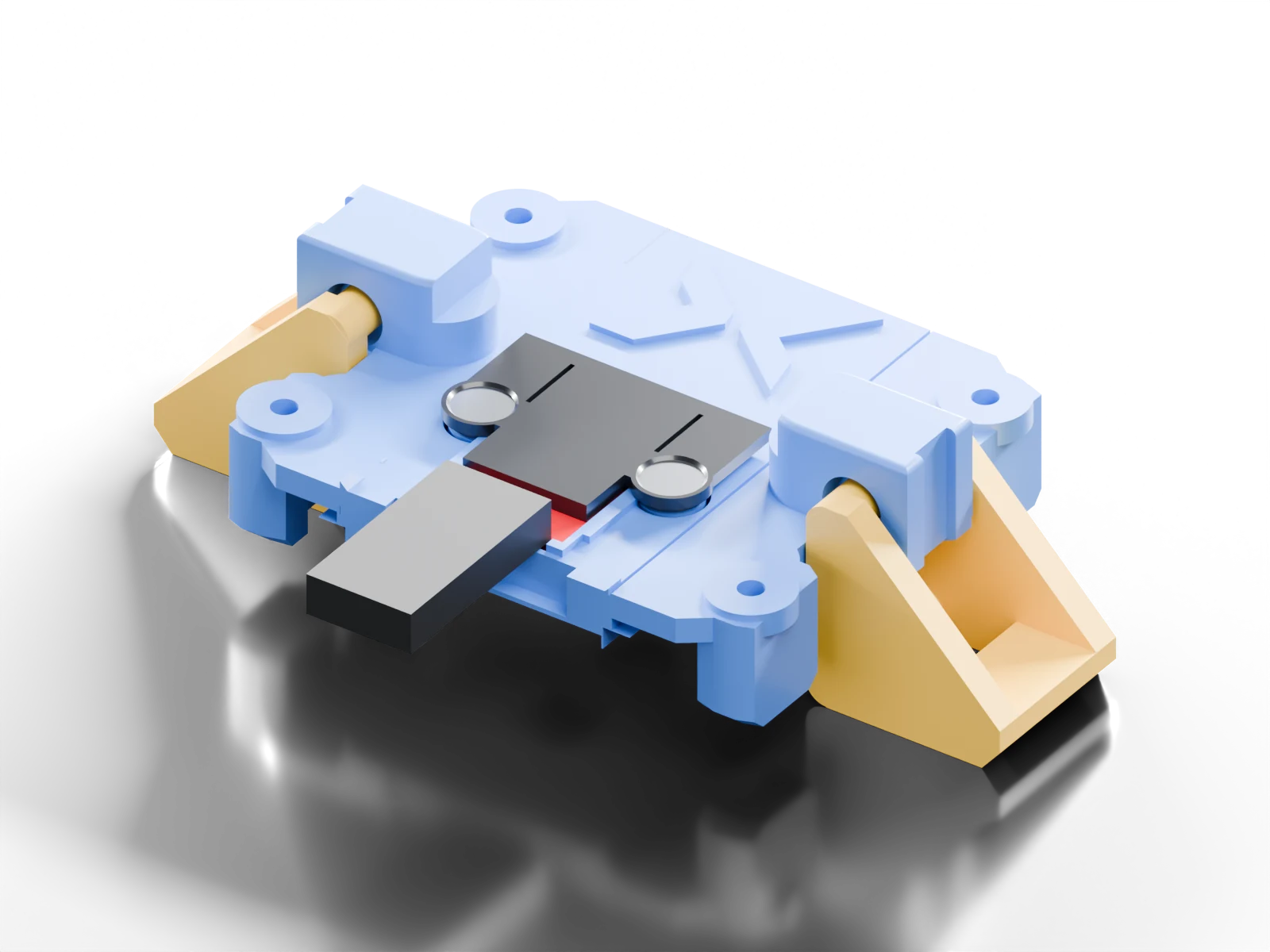
02Fit the QRE1113
Solder a 3-pin right-angle header to the analog ROB-09453 board. Seat it optics-down and fasten the matching sensor retainer.
- 2 × M2×3 countersunk DIN 965 / ISO 7046 · QRE sensor retainer; 90° heads no wider than 3.8 mm
Details
- Top Mount v19 sensor retainer: 2 × M2×3 countersunk DIN 965 / ISO 7046; QRE sensor retainer; 90° heads no wider than 3.8 mm.
- Pan-head screws do not fit these seats.
- Keep the header and sensor lenses aligned with their openings.
Use the Hat 3V3 pin. The Grove port’s red lead is 5 V. 03Wire 3 8 cm leads
OUT to G1, VCC to 3V3, GND to GND. Use 3 8 cm male-to-female wires. Route them through the mount opening with slack clear of the clips.
Details
- Wire with USB unplugged and the M5 powered off. Confirm your board labels.
- The Grove red lead is 5 V; use the Hat 3V3 pin.
- The analog ROB-09453 is the board used for this build.
- 04
Fit the M5 cradle and M5 snap cover
Fasten the M5 to the M5 cradle from below with 2 M2×4 pan-head screws. Attach the M5 cradle to the launcher clamp base with 4 M2×5 pan-head screws, connect the Hat leads and snap on the M5 snap cover.
- 2 × M2×4 pan-head · M5 to M5 cradle, from below
- 4 × M2×5 pan-head · M5 cradle to four 33 × 24 mm mounting pilots
Details
- Keep the wire opening and snap arms clear.
- Press both hooks inward to remove the M5 snap cover.
- Reprint the v19 launcher clamp base with its captive clamps. Reuse the matching v18 M5 cradle, M5 snap cover and countersunk sensor retainer. The lowered middle is 18.2 mm wide with straight sides.
 05
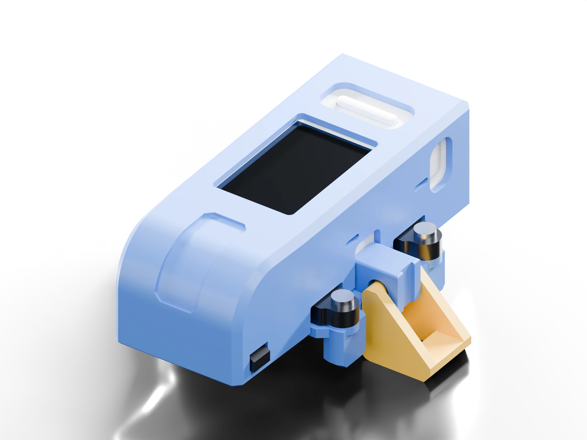
05Clip on and check the fit
Fit the sensor clamps and mount to your string launcher. Check that they hold firmly, nothing rubs, the sensor has a clear view and the wires are not pinched.
- 06
Flash and check
Use the USB updater in desktop Chrome or Edge. Choose First install for a factory M5, then check the version and READY screen.
Details
- Keep a private factory-firmware backup before a first install; the browser cannot make one.
- The updater checks the firmware it writes; test the assembled device with ordinary pulls.
Launcher fit and first installation
Using the device
Short A recalls the latest recap; short B opens history. On history pages A goes to the next page and B returns to main. Hold A on main toggles tournament mode. In Settings, hold B selects a row and hold A changes it.
Older hardware revisions
The earlier v098 QRE base and dock, v097 Sidecar carrier, v069 TCRT sensor and original public packages remain on the downloads page for existing builds. Their screws and assembly differ from this guide.
The earlier public build guide on GitHub covers older hardware revisions. This guide follows the current release.